Difference between revisions of "Kiln"
(→Insulating Fire Brick Repair) |
(→Heating Element Repair) |
||
| Line 115: | Line 115: | ||
If anyone orders replacement kiln heating elements from Paragon Industries in the future, do yourself a favor and place a couple compressions per side in the coils, evenly spaced from each other and the corners, and in pairs 180° apart to correct for angular distortions. | If anyone orders replacement kiln heating elements from Paragon Industries in the future, do yourself a favor and place a couple compressions per side in the coils, evenly spaced from each other and the corners, and in pairs 180° apart to correct for angular distortions. | ||
| + | |||
| + | After a couple runs with the new coils they seemed to shrink slightly. The most heavily compressed regions of the coils seemed to be pulled the most out of their grooves. It is possible Paragon Industries coils may not be an incorrect length when warm. If only we could install them at that temperature. | ||
== Insulating Fire Brick Repair == | == Insulating Fire Brick Repair == | ||
Latest revision as of 00:44, 5 February 2018
We have one and a half kilns.
The whole kiln is an Evenheat 6320-XL.
Kiln Manual: http://www.evenheat-kiln.com/pdf/manual-c-6320xl.pdf
Kiln Setter Manual: http://www.evenheat-kiln.com/pdf/manual-c-kiln-sitter-with-limit-timer.pdf
Kiln Ohmeter Chart: http://www.paragonweb.com/files/manuals/IM20-Ohmmeter%20Readings%20Paragon%20kilns.pdf
Contents
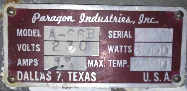
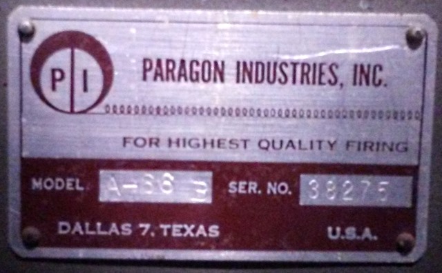
A-66B
The half is a Paragon A-A6-B stacked on top of a Paragon A-66-B, and it's terrible and broken. (it's fixed!... well, it turns on and inefficiently uses the elements. Jury still out on terrible. No more a-a6-b?)
http://www.paragonweb.com/files/wiringdiagrams/A66WD.pdf
http://www.paragonweb.com/files/manuals/IM-5_A_&_B_Inst_&_Service_Manual_July2010.pdf (broken link?)
http://www.paragonweb.com/files/manuals/A_Series_Electrical.pdf
Axner's Supply is 25 minutes from lab and will be a good local resource for supplies and repairs.
Temperature Controller
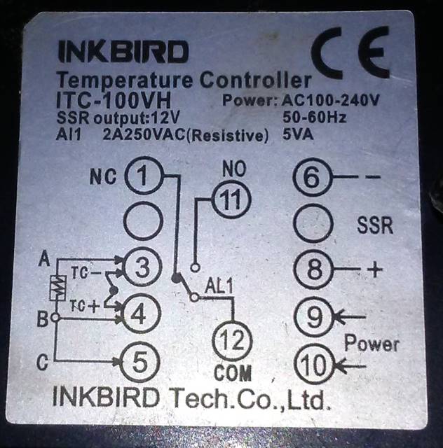
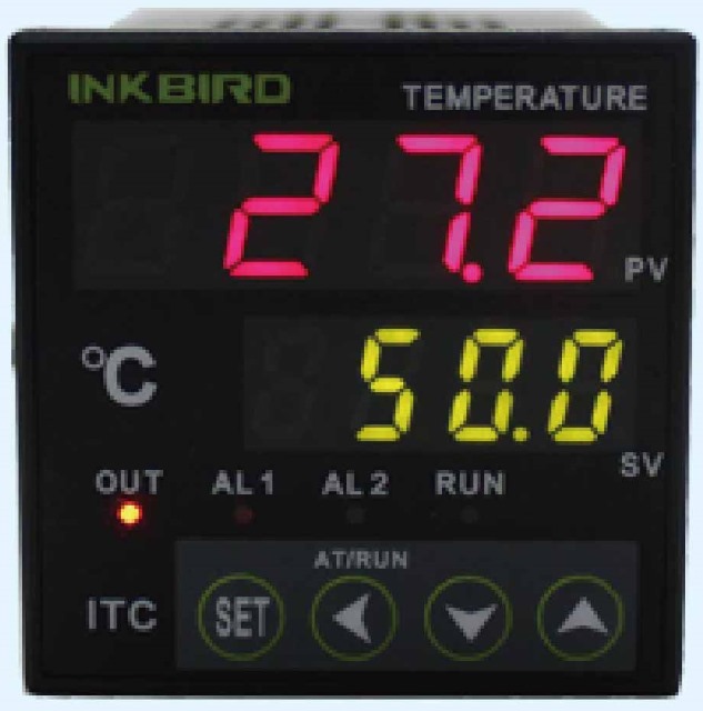
The A-66B kiln uses this temperature controller:
Inkbird ITC-100VH Terminals 1, 5, 11, and 12 have nothing connected to them.
Terminals 9 and 10 are wired to the 240V plug, in parallel with the heating element/solid state relay circuit.
Terminal 3 and 4 are connected to the ridiculously long wires of the thermocouple. I'm not sure if trimming them back would mess with the calibration or not. Or even if the thing is calibrated. Homework for some intrepid individual.
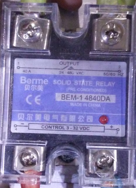
Terminals 6 and 8 go to the solid state relay. It is a handsome fellow, fluent in three languages (if you count "love").
The display on the temperature controller shows the current temperature measured at the thermocouple in degrees Celsius (in red) and the target temperature (in green).
If the current temperature is less than the target temperature, the controller will activate the solid state relay, which connects the heating elements to power.
If you wish to change the target temperature, use the up and down arrows to change the active digit. Using the left arrow, you may select the ones, tens, and hundreds place easily.
You'll notice there are indicators for "AL1" "AL2" "OUT" and "RUN" on the FACE of the display as well. I think I read somewhere this thing can be programmed and AL stands for Alarm. "OUT" seems to come on when the elements are on, maybe it means out of the specified temperature range? I would really like there to be a manual for this somewhere.
The temperature controller may store the target temperature in non-volatile memory. Which is handy, since there is no "off" switch as of yet, the only way to turn off the kiln is to lower the target temperature below ambient or unplug it from the receptacle. When I plugged it back in for the first time since it died, it showed a target temperature of 750°C, the same temperature for pouring aluminum I had set it to all those eons ago...
Diagnostics
Paragon's Instructions on measuring heating element resistance Video
LLKiln's Instructions on The Paper Test
Paper towel scorching from a paper test:
Element Failure Theory
Billions of years ago, microorganisms known as stromatolites evolved a defense mechanism allowing them to toxify the atmospheres of planets with a deadly poison: Oxygen. Where they thrived, other organisms were killed by elevated concentrations of this gas. While this new atmosphere allowed radical new metabolisms to exist, it sucks mad butt for exposed metallic surfaces which promptly oxidize. Beautiful, lustrous metallic crystals are oxidized to brittle, dull powders. Metal didn't even do anything wrong! Why stromatolites gotta be haters? So we grab Ed's knives, jump into the ocean, and carve these little buggers into extinction? Too late. Their photosynthetic legacy has doomed metal to be hidden beneath protective coatings. An unfortunate, added expense of using engineered materials on a biologically active planet.
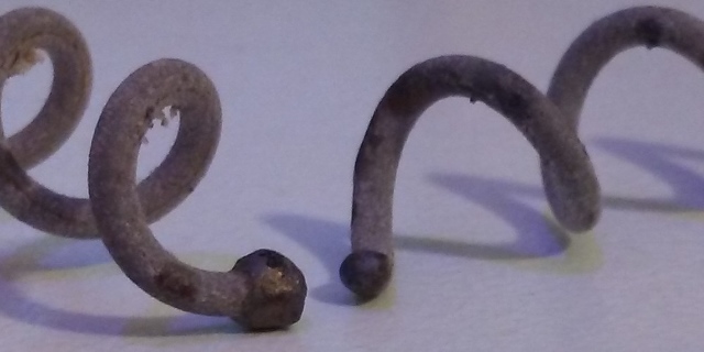
Kiln elements begin to develop an oxide coating as soon as they are exposed to air. This oxidation reaction takes place rapidly at elevated temperatures, such as those found at normal operating temperatures inside a kiln. This oxide coating thickens with use and reduces the exposed surface area to our deadly, deadly atmosphere, slowing the process. With the continued thermal expansion and contraction of the metallic elements, this coating slowly flakes off, exposing more and more metal. This runaway reaction causes the resistance in the elements to increase with use and temperature.
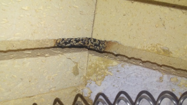
Ultimately, a corroded section of the heating element fails. Mechalich observed if a section breaks while the element is hot, the hot metal begins thermionic emission creating a plasma that vaporizes the metal and briefly allows current to flow through the gap, melting the element further and leaving a glassy coating on the insulating firebrick until the plasma arc extinguishes. This phenomenon can be heard as a 60Hz buzz at the moment of failure.
Corners create hot-spots in the kiln where thermal failures happen first.
Mechanical failure of a corroded element is also possible. The oxidation of the elements leaves them brittle. Like a pretzel stick, it probably won't break under its own weight, but any attempt to bend it will result in a bad time. Only while the elements are red hot do they soften enough to be manipulated back into their grooves.
Heating Element Repair
How To Repair A Bulging Element
Paragon Industries Kiln Heating Element Replacement Video
Old info: I don't know what our kiln's resistance *should* be, but the A-A6-B's coil read at 34.6Ω (prior to Dec 2017)
Late December 2017, the lab received 2 factory-new elements from Paragon Industries for the A-66B. They each have a resistance of approximately 7.5Ω The values were hand-written on the packaging the elements arrived in, presumably after a factory test. Mechalich confirmed this is about right with a sparkfun multimeter, with one element reading about 0.3Ω less. They each came with new screws and barrel connectors for the coils.
Starting from the bottom and feeding the wires into the grooves spiraling up to the top, about 6"-12" of extra coil remained. It was simply too long to fit into the grooves. Maybe paragon industries used a different diameter mandrel to coil the heating element wire on? Maybe it was the same mandrel, but worn down from years of use? Or maybe they didn't have exact dimensions for the discontinued kiln we ordered them for? ¯\_(ツ)_/¯
So what did mechalich do? His best.
Using a pair of pliers to bend the new elements' coils slightly closer together, the overall length of the heating elements started to shrink. It was no easy task. The elements are spirals of hard round wire. There's no easy way to grab that with pliers. Each compression creates an additional angle bend in the wire as well. I discovered if you compress them in one place, then compress them in another place 180° apart, the additional angle bends cancel out and you're left with a wire pointing in the same direction you started with.
Yay! Geometric stability! But wait, *gasp* what about thermal stability? Aren't the compressions creating areas where the coil is more dense, and as such, hotter than the rest? Yes. And the hottest part takes the most thermal stress and fails first. The very act of correcting paragon industries sloppily-manufactured coils shortens their life. There goes my faith in mankind. Again.
Hail Satan
Fear not! Logic and reason give us handles to manipulate a bad situation.
The first coil I learned all these lessons on was the top one. Sadly, all the compressions are close together, near the top of the kiln. I predict this is where the coil will fail.
On the second coil, I realized it too, was going to be too long. Armed with these new coil correction techniques, it was possible to put multiple, evenly-spaced bends in the coil to distribute the thermal spikes over a larger area. Also sadly, multiple compressions ended up occurring at or near corners, which are already hot-spots.
If anyone orders replacement kiln heating elements from Paragon Industries in the future, do yourself a favor and place a couple compressions per side in the coils, evenly spaced from each other and the corners, and in pairs 180° apart to correct for angular distortions.
After a couple runs with the new coils they seemed to shrink slightly. The most heavily compressed regions of the coils seemed to be pulled the most out of their grooves. It is possible Paragon Industries coils may not be an incorrect length when warm. If only we could install them at that temperature.
Insulating Fire Brick Repair
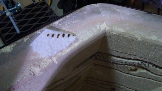
The bricks in the kilns expand and contract with each thermal cycle. It is normal that small cracks will appear in them after prolonged use. A brick that feels loose when cool may fit quite snugly at high temperatures. However, small pieces of a brick may become separated from the kiln due to this process over time.
Replacement bricks may be ordered, as well as a refractory patching compound.
hightemptools makes a refractory compound called APG-36 we used to patch a loose piece of brick where the top element enter the kiln. So far so good.
